Electronic Ignition Coil Wiring Diagram Xr700 Ignition Wiring Diagram
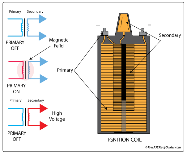
An ignition coil is basically an electromagnet. It has an iron core with fairly thick wire (primary winding) wrapped around it a few hundred times. There is also a secondary winding - about 200 feet of thinner wire coiled between the iron core and primary winding. This winding lies inside the magnetic field created when electricity goes.
Mitsubishi Lancer Ignition Coil Wiring Diagram Wiring Diagram Schemas
This ultimate guide will provide you with everything you need to know about small engine coil wiring. 1. Types of Ignition Systems: There are two main types of ignition systems used in small engines: the magneto ignition system and the battery ignition system. The coil wiring can vary depending on the type of system, so it's essential to.
Ignition Coil Testing Procedure Jeep Cherokee Forum
An ignition coil (or spark coil) is nothing more than a low frequency auto-transformer with a relatively high turns ratio. The transformer typically has only a dozen or so turns on the primary but many thousands on the secondary.. While the circuit diagram is relatively straightforward, it is poorly designed and the transistor will see.
Ignition Coil Technology NGK
What is an ignition coil? This is the part of a car's ignition system that takes the battery's 12-volt output (called low-tension current) and transforms it into as much as 45,000 volts (called high-tension current) before then supplying it to the engine's spark plugs. It is typically just a wire-wound transformer filled with an insulator.
Weak Ignition Coil Causes Misfire
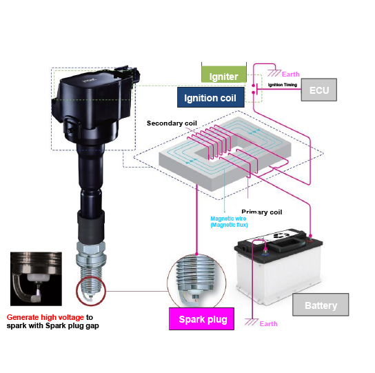
If a coil of wire is exposed to a magnetic field and the magnetic field then changes (or moves), it creates an electric current in the coil of wire. This process is known as 'inductance'. This can be demonstrated simply by moving a permanent magnet across a coil. The movement or change in the magnetic field or magnetic flux induces an.
Electronic Ignition Coil Wiring Diagram Powerspark Ignition Blog The
Auto ignition coils are transformer devices in automobile ignition systems which produce the high voltage necessary to fire the sparkplugs of gasoline internal combustion engines. Remove annotation to coil diagram. The primary winding of the ignition coil is wound with a small number of turns and has a small resistance.
Xr700 Ignition Wiring Diagram
1.1K 92K views 9 months ago The ignition system is a crucial component of any gasoline-powered engine, providing the high voltage necessary to ignite the fuel-air mixture in the engine's.

👉 Wiring Diagram For Ignition Coil ⭐ Jan10
Using a changing magnetic field to induce an electric current If a coil of wire is exposed to a magnetic field and the magnetic field then changes (or moves), it creates an electric current in the coil of wire. This process is known as 'inductance'. This can be demonstrated simply by moving a permanent magnet across a coil.
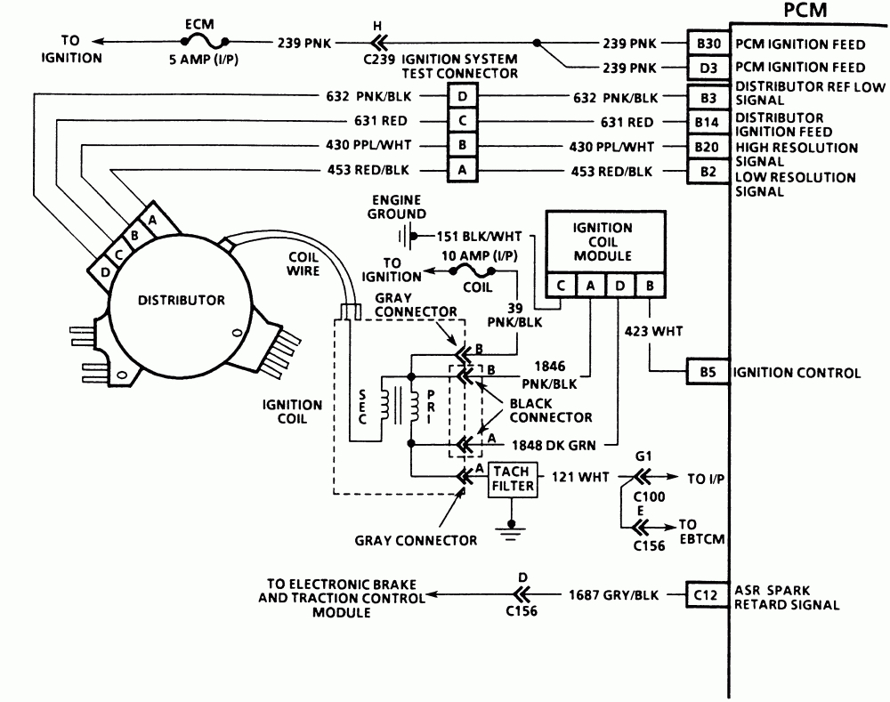
Chevy Ignition Coil Wiring Diagram Cadician's Blog
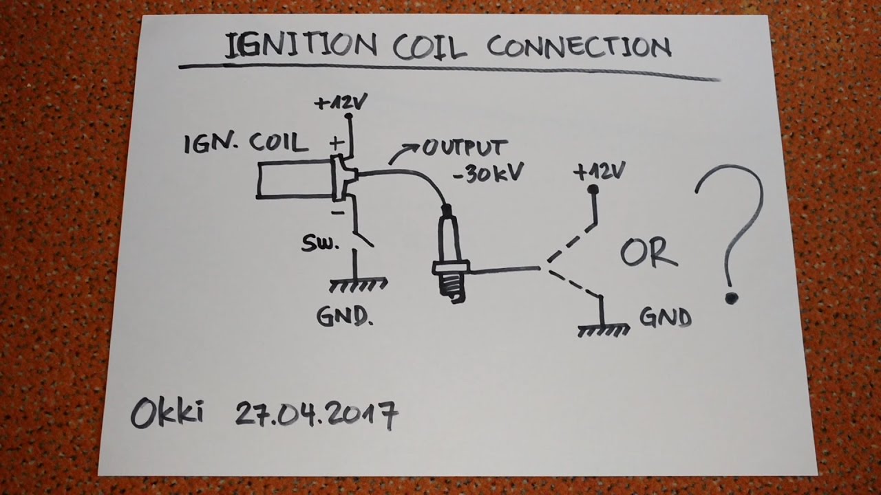
Published on: October 27, 2022 4 min read Contents Below, ill cover the 3-wire ignition coil with a diagram of its wiring and some useful information. The purpose of an ignition coil is to produce high voltage for spark plugs. However, the ignition coil pins must be correctly connected to other electrical components.
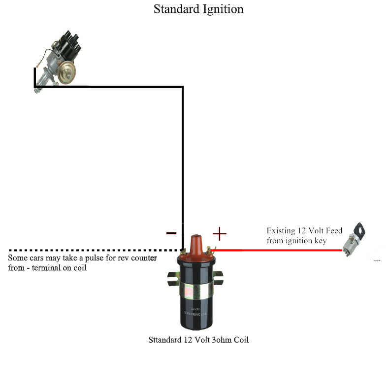
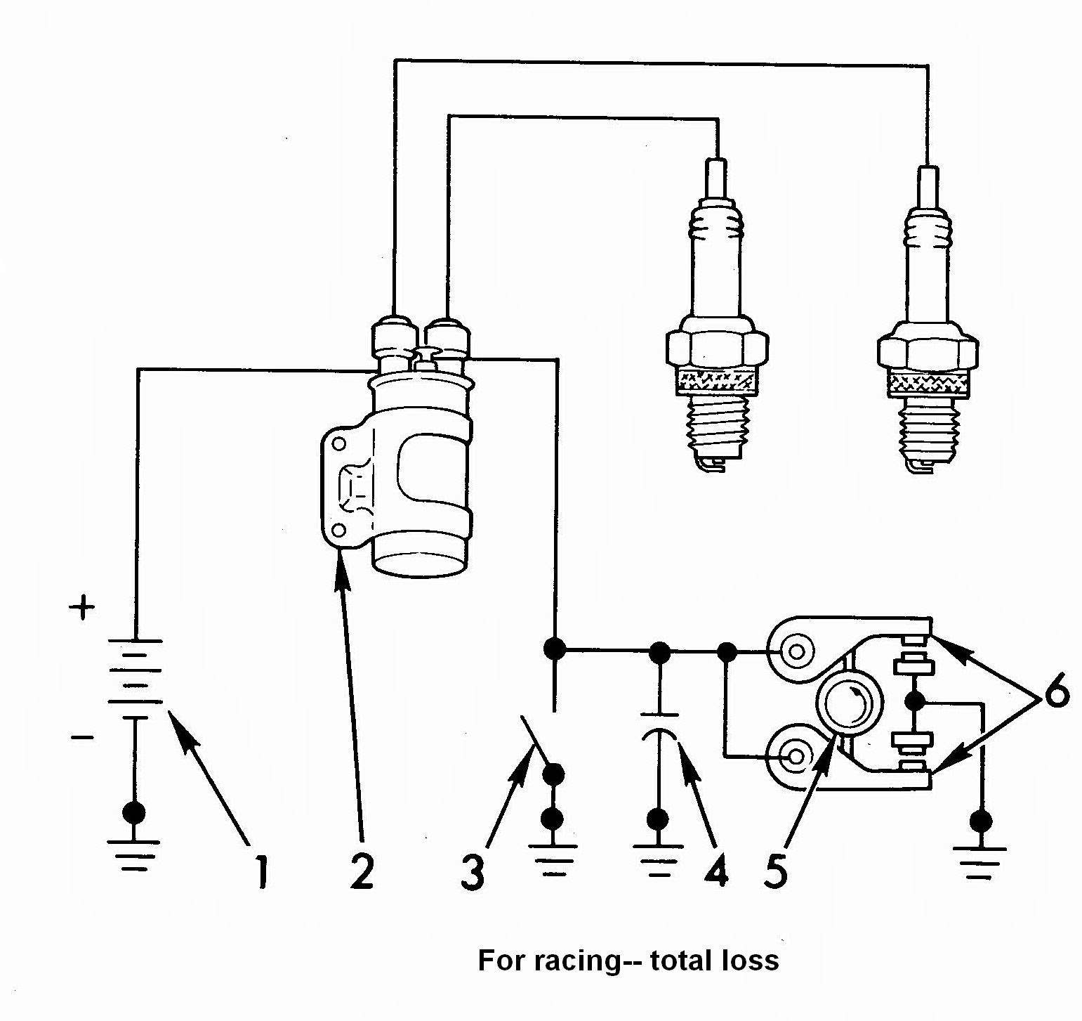
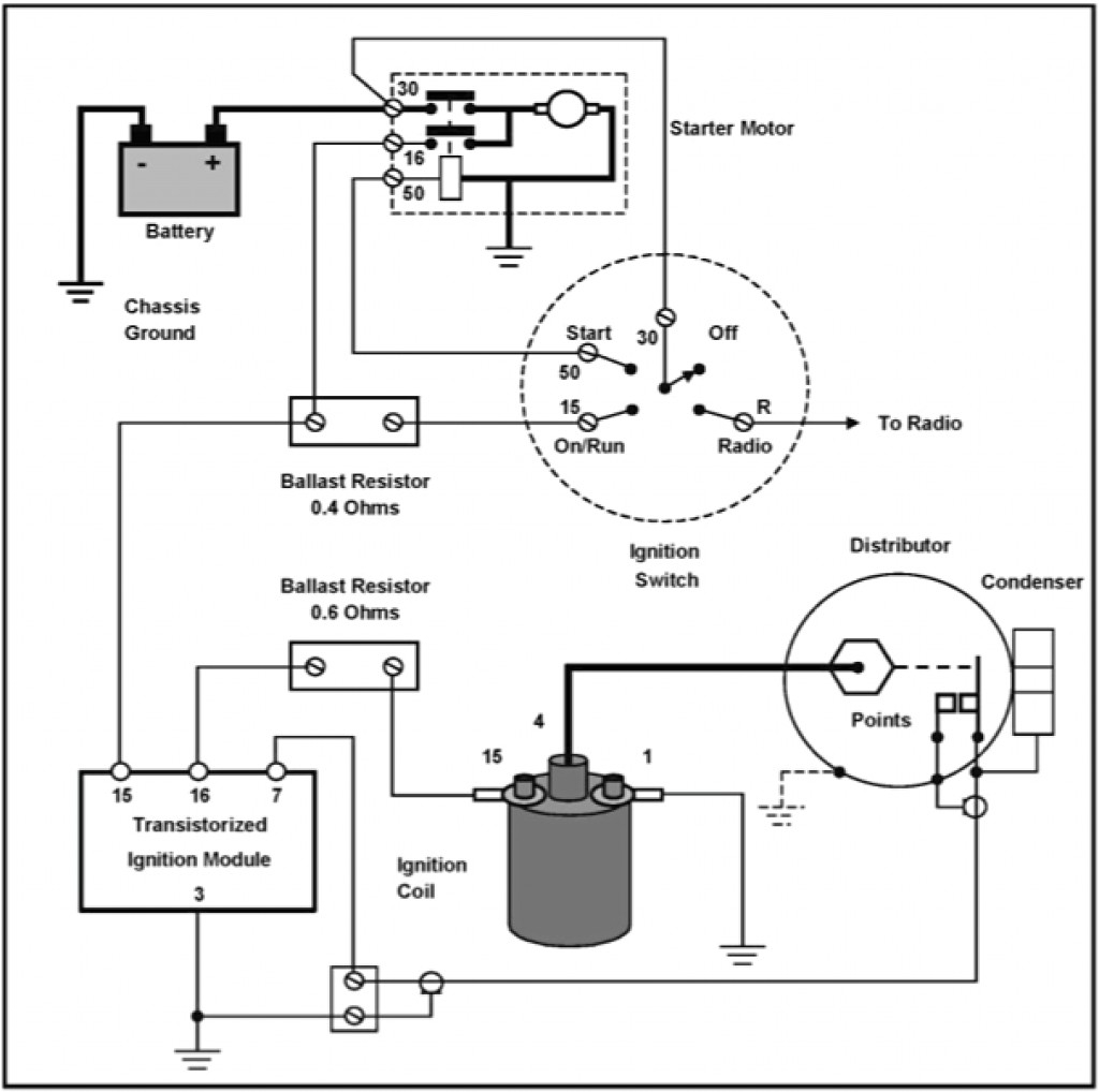
12 Volt Points Ignition Wiring Diagram Handicraftsism
An ignition coil diagram typically includes a schematic representation of the ignition system with the ignition coil at its center. This diagram will show you the wiring connections between the ignition coil, distributor, spark plugs, and ignition wires.

Chevy 350 Ignition Coil Wiring Diagram Free Wiring Diagram
1 Disconnect the negative terminal on your battery. Locate your battery in either the engine bay or the trunk of the vehicle. It looks like a rectangular box with two posts (terminals) sticking out of the top of it. The terminals will be labeled with a plus (+) sign on the positive post and a minus (-) sign on the negative one.
Toyota Ignition Coil Wiring Diagram coil question Page 2 Ford
An ignition Coil is (also called a spark coil) an induction coil which is used to increase the low voltage of the battery (12 Volt) to a very high voltage ( about 50,000 Volt) to produce a spark within the engine cylinder for the combustion of fuel. It is used in automobile ignition systems. We can also say that it is a short step-up transformer.

Chevy 350 Ignition Coil Wiring Diagram Free Wiring Diagram
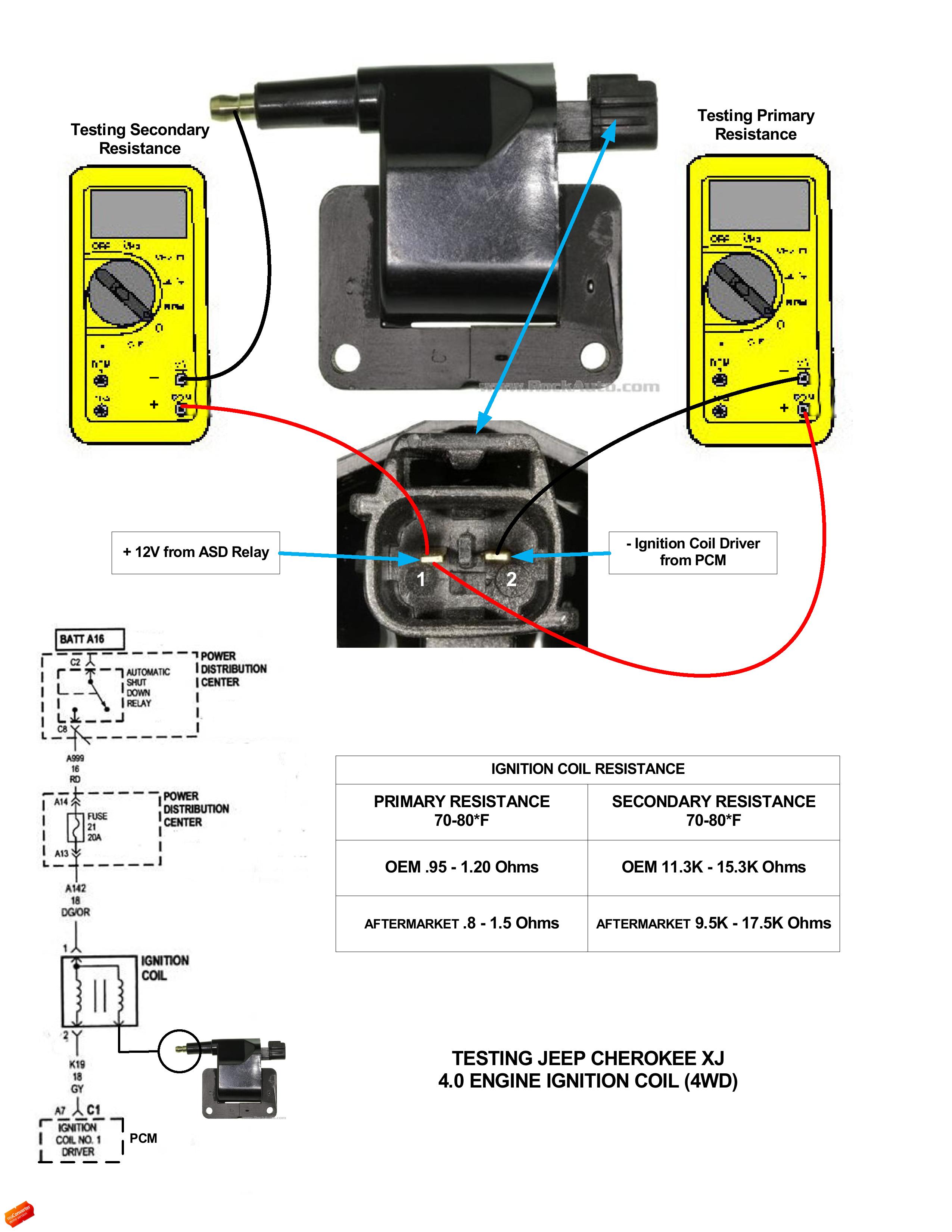
Check voltage supply on the cylinder 3 ignition coil. Remove the connector from the ignition coil. Measure the voltage at the two-pin connector on the wiring harness side. Connect the red cable from the multimeter to PIN 2 (+), and the black cable to engine ground (-). Switch on the ignition.
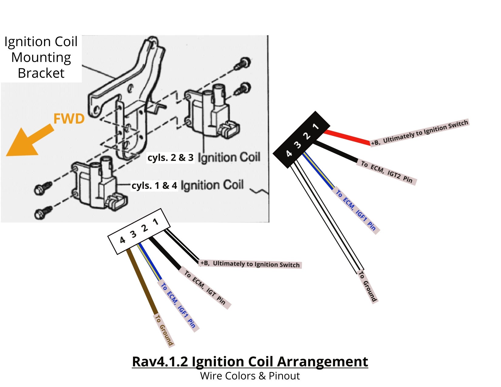
wiring diagram for 98 rav4 Wiring Diagram
December 4, 2023 by Piyushi Dhir In this comprehensive guide, I'll take you through the essentials of ignition control module wiring, a key component in your vehicle's ignition system. We'll explore how to correctly interpret wiring diagrams, understand the functions of each component, and delve into the wiring process itself.

Ignition Coil Main Parts, Working Principle and Application
Contents show The ignition system is one of the most important systems used in the I.C engines. The spark-ignition engine requires some device to ignite the compressed air-fuel mixture. The ignition takes place inside the cylinder at the end of the compression stroke, the ignition system serves this purpose.
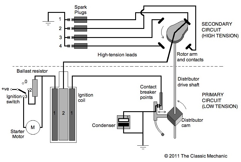
The Classic Mechanic Points/Condenser Ignition Explained
The ignition coil sits between the battery and, if the car is an older model, the distributor that 'distributes' the HT voltage it produces to each spark plug, via thick rubbery HT leads (one per plug). On modern cars with an electronic ignition system that uses a computer, rather than a distributor, to 'fire' the spark plugs at the.
